Most picture tube design engineers agree that a commercially feasible, truly flat CRT--one with no visibly protruding neck structure-- is years away. Nevertheless the past two years have seen enough reduction in picture tube depth to have a strong effect, if not on electrical design, at least on cabinet styling and chassis layout.
To satisfy potential purchasers who want the shallowest possible sets, picture tube depth, until now, has been reduced by progressively widening the deflection angle. However, the practical 110 degree system produces an impasse: further increases of the deflection angle, while attainable, could result in unrealistic receiver prices.
To Philco engineers, therefore, the next logical step was reduction in the length of the protruding CRT neck. The successful result of their investigation is the 110 degree SF (semi flat) picture tube. shown in Fig. 2 directly under a conventional 110 degree CRT having the same screen area. The reduction attained varies from one CRT size to another, but generally runs close to two inches. In part, this was achieved by bringing the electron gun assembly in toward the bell of the tube, but the greatest factor has been a re-design of the gun assembly itself.
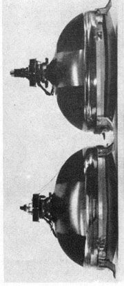 Fig.2
Fig.2
With the difference in gun size and positioning, the relationship between the deflection yoke and the beam it must influence also changes. Here we have another problem, which is indicated, to some extent by Fig.2. In the lower part of the photograph, the base of the SF tube and a small portion of its neck barely protrude from the yoke assembly, and the yoke itself is in closer against the bell as compared with the yoke on the conventional 110 degree CRT at the top. With this changed relationship, yoke winding parameters also had to be reconsidered. The result is a coil assembly that is wound to maintain high deflection efficiency with no sacrifice in over-all focus. Most important, this change involved no great cost increase.
As with the yoke, it was important that the picture tube could be produced at a price competitive with existing types. This was achieved despite the fact that the method of evacuating and sealing the CRT had to be altered. With conventional techniques, this operation would damage the heater-cathode assembly, which is quite close to the base of the SF tube.
With the tube and yoke out of the way, the rest of the job involving the set itself would appear to be largely out of the hands of the electronics department. This was true to a great extent, but not entirely. The l7-inch portable segment of the 1959 Philco line consists of handle-on-the-top receivers styled along the lines of the common briefcase. Contributing to the slender appearance is the "wraparound" chassis, which is contoured about the SF tube and adds nothing to the depth of the housing itself.
For the larger, non-portable receivers, chassis layout is somewhat more conventional, but the external appearance of many of them is unusual. The CRT is in a separate housing made of high-impact plastic, transparent over the viewing area, and appearing to have been molded around the picture tube. This housing swivels, much in the manner of certain vanity mirrors, so that it can be adjusted to the most convenient viewing position. Chassis and operating controls are built into a separate compact cabinet, available as a table-top unit, on legs in a lowboy style, or in an upright "pedestal" model. In each case, the CRT housing is mounted on top of the cabinet.
In one variation shown in Fig.1 (above) the receiver connects to the picture tube housing through a 25-foot, multiconductor cable. This permits flexible placement of the CRT about the room away from the chassis. Since signal, second-anode, filament, deflection, and other voltages must all be carried in this cable, adequate insulation as well as shielding to prevent cross-talk had to be worked out carefully. Both cable and CRT housing meet UL requirements.
A video signal fed directly through such a cable would deteriorate seriously, so once more the electronics men stepped into the picture. A low-impedence cathode follower at the main chassis feeds the signal through the cable to a video driver tube mounted near the neck of the CRT. This, in turn, feeds the picture tube.
As for reciever circuit design, Philco's 1959 line involves no radical changes, closely resembling its 1958 line.
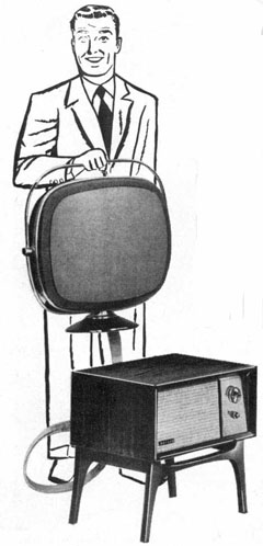 Fig1.
Fig1.
In conventional picture tubes, the cathode -heater portion of the gun involves a cylindrical structure. Philco engineers have abandoned this assembly, using instead a Mica supported box frame. As can be seen in Fig.3, this makes the gun much shorter.
At the right of Fig.3 is a gun from a 90 degree tube. Immediately to the left of it is the somewhat shorter gun assembly used for earlier 110 degree designs. Size and spacing of the electrodes show a reduction as compared to pre-110 degree CRT's. In the gun for the SF tube, shown at the left of the illustration, only the cathode-heater portion has been changed significantly as compared to preceding 110 degree types. Nevertheless, the space saving obtained with this measure is greater than that realized the first step from 90 degrees to 110 degrees.
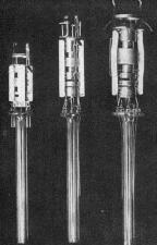 Fig 3
Fig 3